Hercules JXD connecting rod modification
This conversion process is designed to work on undamaged rods and should not be attempted as a method to "save" damaged parts. The purpose of these modifications is to improve the strength of the rod cap attachment and accuracy of bearing fit while eliminating the use of adjustment shims.
Any connecting rod caps or beams that have wallowed out rod bolt holes or hammer damage or excessive damage to the parting line face should be rejected. Because these rods have insert type bearings, yet are designed to be assembled with wear shims by a cotter key retained nut, there is a large possibility of having been run too loose or too tight at some time. A shim may have fallen out, or a backed off nut may have caused fretting damage. Because there is essentially no material between the rod bolt hole and the bearing insert at the parting line, a spun bearing shell may ruin these rods for rebuilding where similar damage to a rod with more material in that area might be re-machined. Because they are of a "loose bolt fit" style there is a large chance they were also misaligned at some point, causing damage to the rod bolt holes or parting line surfaces or big end side clearance surfaces. Therefore each rod may have different causes for rejection which are discovered as the conversion process is implemented and odd wear patterns become apparent.
The conversion steps begin with disassembled rods, down to a naked beam and cap, and then cleaning and magniflux inspection of all parts. The rod beam bolt holes at the big end are next reamed to .440 inch dia. A piloted reamer is necessary so the alignment of the hole remains unchanged. Any beams with rod bolt holes that were wallowed out or are already oversize when reamed should be rejected as damaged or unusable parts.
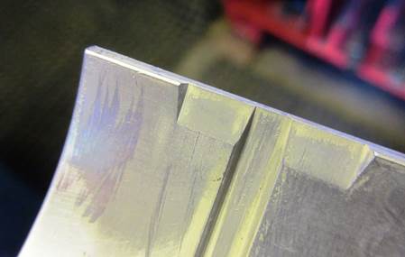
 The rod beam parting
line faces need to be ground on a Sunnen precision Cap Grinder using a
#CRG 305
course grit cup wheel at .002 inch per pass stock removal, hand fed,
until just
cleaned then sparked out against the grinding wheel. The beams should
be
lightly hand lapped against a diamond lap bar to improve surface
finish. The
inner edge of the parting line should be hand draw filed to create a
chamfer to
allow an insert bearing to be more easily slid into place and to de-burr the inner edge. Chamfers should be
created on the
bolt hole exit areas by using a 45 degree cutter hand fed in a drill
press, in
a milling vice, against a wood block cushion. The rod beams can then be
set aside
so new bolts can be prepared.
The rod beam parting
line faces need to be ground on a Sunnen precision Cap Grinder using a
#CRG 305
course grit cup wheel at .002 inch per pass stock removal, hand fed,
until just
cleaned then sparked out against the grinding wheel. The beams should
be
lightly hand lapped against a diamond lap bar to improve surface
finish. The
inner edge of the parting line should be hand draw filed to create a
chamfer to
allow an insert bearing to be more easily slid into place and to de-burr the inner edge. Chamfers should be
created on the
bolt hole exit areas by using a 45 degree cutter hand fed in a drill
press, in
a milling vice, against a wood block cushion. The rod beams can then be
set aside
so new bolts can be prepared.
ARP # 35-6001 connecting rod bolt sets (Big Block Chevy) were chosen because they are the closest "pre-engineered" bolt made which could be modified to fit space available on the Hercules connecting rod bolt head area. The rod bolt modification is to remove, by vertically grinding off, a small amount of material on the inboard side of the bolt head to create .020 inch minimum clearance between the bolt head and the bolt head pad machined into the rod beam. This will prevent stresses and distortion when these bolts are installed which would cause the rod beam to break when in service. Grinding just the inboard side of the bolt head flush with the bolt shank will achieve that clearance.
The modified bolts, when matched to the reamed rod beam holes, yields a .002-3 interference fit to the rod bolt knurled area. The press fit is assembled dry at 1&1/2 to 2 tons force while held square and perpendicular in and against an aluminum fixture to prevent thread damage. The beams should then be set aside so work on the caps can begin.
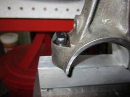
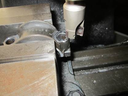
The rod cap parting line surfaces should be ground and chamfered in a similar way to the connecting rod beams and organized in a tray for spot facing of the nuts load bearing area. Note: Do NOT ream the cap bolt holes. A cap spot facing milling tool to correct rod nut seating geometry will allow a hardened load bearing washer to be installed. I eventually chose a milling cutter from MSC, item #86482931. That grade of cutter was needed because these rods are forged from very, very, tough steel which instantly dulls a lesser tool. The MSC cutter is 1 inch dia x 3/4 inch shank, CNC center cooled, 3 insert hi-pos rake milling body, running 3 #75201731 double ended carbide inserts.
 (This
is a $465.00 dollar cutter which I would
have considered total overkill until I wrecked a 1 inch by 3/4 HHS 6
flute
cobalt coated end mill, and wrecked a similar tool coated in titanium
while
working my way back up the line of tool hardness after testing with a
solid
carbide 3/4 by 3/4 end mill that cut well but was the wrong size). They
were
run at 1600 RPM. The feed was less than .030 for a single cut at
.050 inch
per second cross feed to just clean the area to fresh metal. A few rods
required an additional .020 cut to clean completely. Spray mist WD-40
was used
as a coolant and lube.
(This
is a $465.00 dollar cutter which I would
have considered total overkill until I wrecked a 1 inch by 3/4 HHS 6
flute
cobalt coated end mill, and wrecked a similar tool coated in titanium
while
working my way back up the line of tool hardness after testing with a
solid
carbide 3/4 by 3/4 end mill that cut well but was the wrong size). They
were
run at 1600 RPM. The feed was less than .030 for a single cut at
.050 inch
per second cross feed to just clean the area to fresh metal. A few rods
required an additional .020 cut to clean completely. Spray mist WD-40
was used
as a coolant and lube.
This worked out OK but still required hand de-burring with a Dremel tool running a 180 grit (fine) stone. The caps bolt entry and exit holes were chamfered with a 45 degree tool hand fed in a drill press against wooden blocks. The caps should then be set aside so hardened washers can be prepared for the modified connecting rod assemblies.
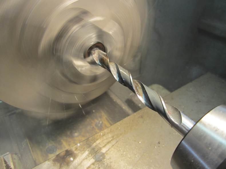
Hardened washers are needed for this conversion to space the ARP nut away from bottoming out on the last thread of the bolt, which is where the nut would seize without a washer, causing premature failure of the assembly. Seizing of the thread prevents proper tension on the bolt causing the assembly to fail. The washer must fit the bolt snugly, be at least .100 thick, and clear the spot faced area. Therefore it’s ID should to be .002 larger than the bolt’s .4375 OD to just slip over the bolt, but smaller than .453 (the next larger drill size). And have an outside diameter of less than 1.000 inch to fit the spot faced area. These are not standard hardened washer dimension pairs. A .4375 washer has an OD which is too large. A washer with a slightly smaller than 1.000 inch OD has a hole which is nominally .3750. One path to a solution is to drill out a washer with a .375 center hole to .4395 inch. The difficulties are; this is not a standard drill size, and that the washers are hardened, so they are impossible to drill on size, and time consuming to bore with carbide tooling. A solution is to friction drill the holes to .4375 and when cleaning up the melt ridge and distortion you end up gaining the needed .002 clearance to fit over the bolt thread. In this case the melt ridge was removed by surface grinding on a magnetic table and ID de-burring was done with a Dremel tool. An alternative but time consuming process would be to grind the ID with a small stone (similar to one used to sharpen chain saw chains) until the correct size is reached. The connecting rod conversion processes are now completed for the rod sub-assemblies and regular rod re-sizing procedures can be attempted once they are put together. However some comments about issues specific to these connecting rods should be considered first.
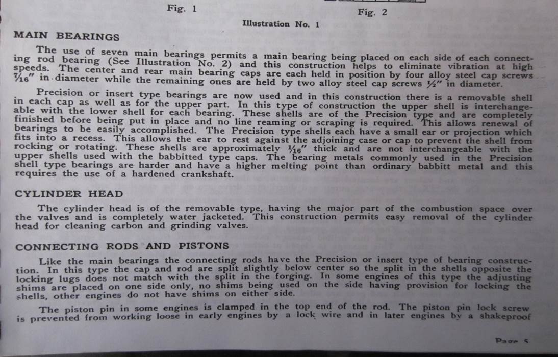
These Hercules connecting rods do NOT have the big end bearing housing bore parting line at the exact midpoint of the bearing bore in relation to the bearing insert parting line location. They are engineered to have the insert extend past the parting line on the cap side about .075 inch and be countersunk on the beam side an equal amount creating a nesting or interlocking relationship between the cap and beam inserts and housing bore halves. This relationship promotes alignment of the pairs when assembled. It also prevents a bearing clearance adjusting shim from being installed too deep into the parting line area and rubbing against the crankshaft. I believe preventing excessive penetration of an adjustment shim is a reason adjusting shims are restricted to placement on only the interlocking side of the housing bore. An excerpt from the factory service manual is shown below; reference the last section, first paragraph, titled “Connecting Rods and Pistons”.
 This interlocking
relationship is created by the diameter of the rod housing bore size,
the
bearing insert length, and allowed by the insert bearing shells
locating tang
fitting flush into a recess cut into the housing bore while being level
with
the parting line only on that side. In an OEM assembly the amount of
interlock
will be adjusted by installing shims which change bearing running
clearance in
relation to the crankshaft. For ease in general engine assembly, and
because
most of the reasons to provide for adjustable bearing clearance have
been
superseded with modern technology, eliminating use of the clearance
adjusting
shims is very desirable. So the following procedures should be
considered and
implemented.
This interlocking
relationship is created by the diameter of the rod housing bore size,
the
bearing insert length, and allowed by the insert bearing shells
locating tang
fitting flush into a recess cut into the housing bore while being level
with
the parting line only on that side. In an OEM assembly the amount of
interlock
will be adjusted by installing shims which change bearing running
clearance in
relation to the crankshaft. For ease in general engine assembly, and
because
most of the reasons to provide for adjustable bearing clearance have
been
superseded with modern technology, eliminating use of the clearance
adjusting
shims is very desirable. So the following procedures should be
considered and
implemented.
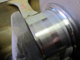
A primary factor in creating long bearing life is having and keeping the crankshaft round and at a specific size called out in the manufacturer’s service specifications. A good crank grinder can easily do this on modern grinding machinery so Hercules crankshafts considered for this modification should be carefully examined and either polished or ground exactly to the mid-range of standard size limits. Replacement bearings are of high quality so should be used after cleaning, without attempting to trim or re-size them. The connecting rod housing bores need to be re-machined on a Sunnen Precision hone so the exact fit of insert bearings to the connecting rod is made by controlling the housing bore diameter. Housing bore size should be set at the low limit of factory specifications, 2.1345, plus .0005 / minus 0.0, to provide maximum retention of the bearing inserts. Because a considerable amount of material is usually removed when grinding the housing bore parting line surfaces (.010 or more) CR10 Sunnen roughing stones will be needed to initially hone the housing bores round. This will typically occur when they are brought within .004 inches of being at size. Switching to CR12 finishing stones will promote improved surface finish and prevent rapid material removal which could lead to creating oversize housing bores. When these crank and housing bore sizes are achieved, and the proper size insert bearing is installed, the bearing oil clearance will be .001 inch. This clearance will work with all modern (diesel) truck engine oils. Keeping the engine oil clean and crankcase pressures low (to prevent leaks) by installing a closed crankcase PCV system and a crankcase breather system to the air cleaner is highly recommended.
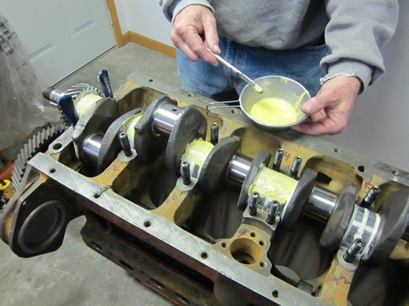
 Assembly
of the connecting rod bearing inserts
into their housing bore halves require seating the insert shell flush
ONLY at
the tang end and solidly around the circumference of the housing. All
protrusion or countersunk length should accumulate on the opposite
side. A
fixture can be made to do this which slips over the rod bolt threads
and
flushes against the tang side of the parting line and bearing shell
while not
covering the insert shell on the opposite side. Starting the bearing
about a 1/4
inch high on the tang side will allow the fixture to push the shell
into the
correct position with hand pressure.
Assembly
of the connecting rod bearing inserts
into their housing bore halves require seating the insert shell flush
ONLY at
the tang end and solidly around the circumference of the housing. All
protrusion or countersunk length should accumulate on the opposite
side. A
fixture can be made to do this which slips over the rod bolt threads
and
flushes against the tang side of the parting line and bearing shell
while not
covering the insert shell on the opposite side. Starting the bearing
about a 1/4
inch high on the tang side will allow the fixture to push the shell
into the
correct position with hand pressure.
Assembly of the cap side bearing insert is similar except two dummy bolts should be installed into the assembly fixture to simulate connecting rod cap bolts. These dummy bolts will promote alignment of the cap against the fixture.
When the engine rotating assembly is installed in the crankcase it is imperative the interlocking relationship between the shells and housing bores is achieved. It is sometimes possible to install the bearing caps so the bearing inserts butt together prematurely instead of sliding into an interlocking fit first. This incorrect fit up will cause the bearing inserts to buckle and lock against the crankshaft when tightened. Bearings which buckle to any degree are ruined and should be discarded. A second assembly issue concerns a bearing insert that may rotate slightly when pushed together in an attempt to force the shells to interlock. If a rotated bearing is tightened the tang area will be out of position. The tang relief area will become ineffective causing a distortion of the bearing shell. This will also result in crankshaft bearing failure. A correct fit will be manifest by observing clearance at the cap parting line of about .003 inch before tightening the connecting rod nuts into significant tension.
Incorrect fit will be manifest by about .075 inch or more clearance when the cap is in place ready to be tightened. A correct fit will be manifest after the bearing is tightened by sliding the connecting rod slightly, with light hand pressure, as connecting rod side play on the crankshaft journal is verified and measured. Incorrect fit will prevent the rod from moving freely.
This text and photo article was created by Fowler Automotive. www.fowlerautomotive.com all rights reserved.